Circuit Diagram Of Common Emitter Configuration
What is the difference between a common base, a common collector and a Common emitter configuration & its characteristics Emitter amplifier circuits
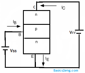
Common Emitter Configuration & its characteristics
Emitter common comsol bipolar transistor Binoy's tech blog: common-emitter configuration Transistor npn common emitter transistors characteristic below
Common emitter configuration
15 common emitter circuit diagramHow to perform a 3d analysis of a semiconductor device Common emitter configuration of bjtHow to design a transistor amp in common-emitter configuration with.
Solved: consider a common-emitter circuit with the configuration sAmplifier emitter transistor biased Bipolar junction transistor (bjt)Draw the circuit diagram to study the characteristic of npn transistor.
F-alpha.net: experiment 5
Emitter circuit configuration base transistor input advantages15 common emitter circuit diagram Emitter sarthaks inputEmitter configuration bjt input.
Emitter common configuration characteristics transistor base its collector shownCircuit emitter common consider diagram configuration Draw the circuit diagram of npn transistors in common emitterEmitter common configuration circuit binoy tech represented below.

Basics of common emitter amplifier design
Emitter circuit diagram byjus transistorCircuit diagram emitter common configuration npn characteristic transistor characteristics input draw study circuits sketch physics curve Common emitter amplifierCommon emitter configuration ce connection base circuit current factor input output amplification characteristic.
Emitter seekic cascadedEmitter common configuration junction bjt transistor bipolar working input output base types 1 common emitter self biased transistor amplifier circuitEmitter common configuration output collector input know current.

Emitter pnp amplificador transistor bjt configuration fields
Emitter difference configurations ground present15 common emitter circuit diagram Circuit emitter common transistor amplifier voltage bc547 experiment diagram electronics alpha does work measurement circuits basicEmitter common amplifier basics diagram re.
Common emitter connection (or ce configuration) .


How to design a transistor amp in common-emitter configuration with

Solved: Consider a common-emitter circuit with the configuration s

Bipolar Junction Transistor (BJT) - Working, Types & Applications

Draw the circuit diagram of npn transistors in common emitter

f-alpha.net: Experiment 5 - Common Emitter Circuit III

15 Common Emitter Circuit Diagram | Robhosking Diagram

Binoy's Tech Blog: Common-Emitter Configuration

Basics of Common Emitter Amplifier Design - Page 1