Circuit Diagram Voltmeter Potentiometer
Voltage divider circuit dc dividers breadboard potentiometer circuits resistors series potentiometers wire led resistor need electrical wiring measurement schematic work Potentiometer circuitstoday Potentiometers potentiometer wiring principles passive linear
resistance - Need help putting two potentiometers in series
Why changing the potentiometer affects the whole circuit? Reading a potentiometer with an unknown voltage Potentiometer connection, circuit diagram, wiring guide
Calibration of voltmeter, ammeter & wattmeter using potentiometer
Solved calculate how the output voltage range would changeVoltage potentiometer calculate range divider load schematic variable change circuit output would resistance parallel questions explain significance effect loading source Calibration of pmmc voltmeter using a potentiometerPotentiometer fizzics.
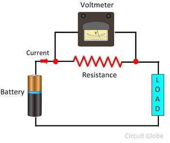
Potentiometer wire connection 10k ohm linquipAmmeter voltmeter electricity physics Series two potentiometers circuit schematic putting need help usingPotentiometer difference voltmeter between circuit circuitglobe.

Voltmeter potentiometric schematic node spice numbers
S-curve using linear potentiometer without huge power drainWiring diagram potentiometer Potentiometric voltmeterSimple circuit diagram gone ammeter and voltmeter.
Voltmeter diagram potentiometricDraw a well labeled circuit diagram of a potentiometer to measure the Potentiometer reading schematic voltage unknown circuit circuitlab created usingCalibration voltmeter using potentiometer circuit pmmc diagram magnet permanent coil moving.
12v potentiometer schematic circuit circuitlab created using stack
Difference between potentiometer & voltmeter (with comparison chartLinear potentiometer Simple digital voltmeter circuit diagram using icl7107Potentiometers – basic principles – passive components blog.
Voltmeter measuring circuit panel voltmeters analog diagrams 4uPotentiometer comparing differences Voltmeter differential basic circuit constructionVoltmeter parallel voltage circuitglobe.
.png)
Potentiometer circuits voltage finished when
Analog circuits trainingWhat is differential voltmeter? Dc labPotentiometer circuit schematic affects changing whole why circuitlab created using.
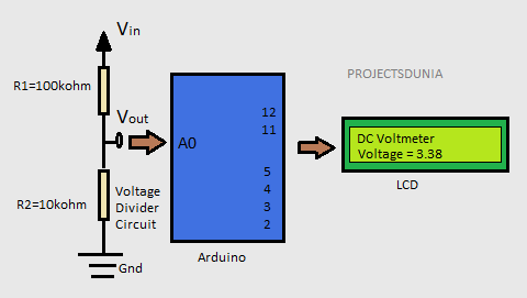
Potentiometer linear using circuit curve drain huge without power schematic nonLearn how to make a digital voltmeter using arduino A potentiometer circuit that is used as a means of comparing potentialPotentiometer labeled resistance physics ammeter.

How to wire voltmeters for 3 phase voltage measuring
Potentiometer linear wiring diagramPotentiometers explained Calibration of voltmeter, ammeter & wattmeter using potentiometerWhat is voltmeter?.
Calibration voltmeter circuit potentiometer ammeter using voltage adjustmentVoltmeter arduino dc diagram using digital block make circuit based learn Voltmeter circuit diagram digital using simple icl7107 voltage ic low electronic circuits led build board measurement pcb projects arduino chooseAmmeter potentiometer calibration voltmeter using resistance wattmeter circuit standard resistor current voltage calibrated connected series which used.


Potentiometer Connection, Circuit Diagram, Wiring Guide | Linquip

Potentiometric Voltmeter | DC Circuits | Electronics Textbook

DC Lab - Potentiometric Voltmeter | DC Circuit Projects | Electronics
What is Voltmeter? - Definition & Types - Circuit Globe

Calibration of PMMC Voltmeter Using a Potentiometer

resistance - Need help putting two potentiometers in series
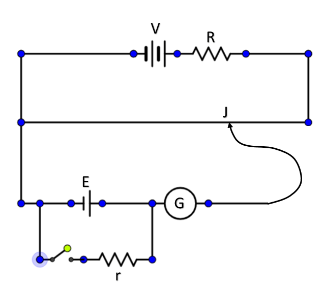
Draw a well labeled circuit diagram of a potentiometer to measure the